Modern manufacturers require optimized and customer-satisfying models produced quickly. Design constraints must be met before moving to production, and more designs must be explored. A tool that can fulfill these critical requirements is sought after by all manufacturers.
CAD Morpher, available in MeshWorks, is a game changer, offering faster CAD model building than ever before. It can handle both CAD and CAE models, making it the perfect bridge between design and CAE teams. Optimized Finite Element and CAD data can be communicated directly to the design department as morphed CAD data, allowing for the creation of multiple designs with various specs and constraints in less time.
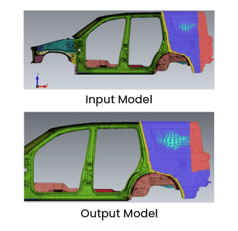
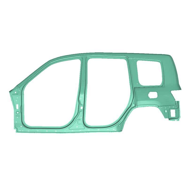
MeshWorks CAD-Morphing is a transformational feature that allows users to efficiently modify existing CAD data of a product directly to new shapes. For instance, BIW CAD data for an existing production vehicle can be morphed and fit to a new vehicle’s styling data and/or proportions. This is possible for all auto parts such as body structures, powertrain, chassis, and more. Our patented CAD morphing technology can reduce several months of CAD development.
Typically, FE modeling and simulations are done once the concept CAD is generated. To reduce design iterations, it would be helpful if concept changes could be made in the FE model itself, eliminating the time required for CAD generation. This can be achieved through CAE Morphing. Morphing involves adapting a given shape to a new form, as is done in mesh morphing. The donor model can be modified to required proportions using morphing techniques to create new designs.
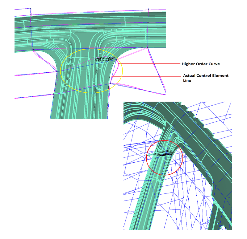
DEP MeshWorks’ powerful CAE function includes a feature-based morphing tool that can quickly morph existing FE and CFD models to match new geometry and/or proportions. Full system level FE/CFD models, such as automotive vehicle crash, NVH, and durability models, can be morphed to fit target design features, precisely. There is a variety of built-in morphing techniques, including control block (lower and higher order), direct parabolic, spherical, polycube, and field-based morphing. An extensive set of automated and interactive tools to create “control blocks” for assembly-level morphing is available.
How CAD Morphing Works:
- Step 1 involves the recording of CAE morphing steps where the entire history of morphing is saved and appropriate sequences are remembered and saved. The CAE resolution is then modified to match the CAD resolution.
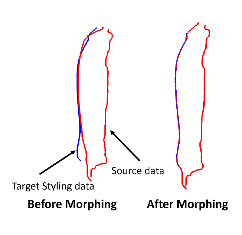
- In step 2, the multi-step morphing history is executed on the original CAD data where the morphing history is applied step by step on every part of the original CAD data. After each morphing step, the quality of the morphed CAD data is evaluated and the resolution parameters are adjusted to achieve the best quality.
- Step 3 involves the conversion of the morphed IGES DATA to the native format (CATIA). Our engineers have developed a well-defined process for this conversion, which involves executing a sequential process of CATIA operations using a particular method by the CAD designer. The resulting CAD geometry element is of production quality.
Functions and Applications:
- MeshWorks offers a range of techniques for morphing 2D and 3D meshes using FE Morphing.
- There are also several user-friendly and efficient methods for creating control blocks.
- Manual Control Block creation.
- Auto Control Block creation.
- Control Block using 2 planes.
- Blocks using curves and sections and various other methods of block creation.
- Free-Form (direct) Morphing for more control over the geometry.
- Diverse Morphing options such as:
- Free-Form & Control Block method
- Poly Cube Morphing
- Curve based Morphing
- Pattern Morphing
- Stretch Morphing
- One time execution of required changes can be easily carried out with use of any one of the morphing methods.
- Transformations can be parameterized and saved to generate multiple designs.
- DOE files can be utilized to create numerous designs.
- Full control over various parameters allows for increased flexibility and reduced design generation time.
- The software is compatible with a wide range of solvers and platforms, allowing for solver-dependent template creation.
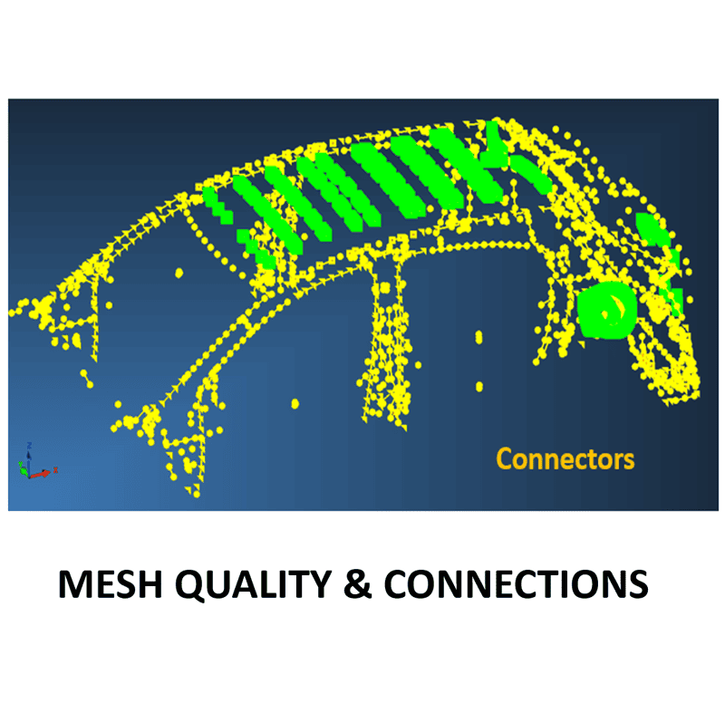
- Optimization of joints (Welds/Rigids) can be performed within and between morphing components.
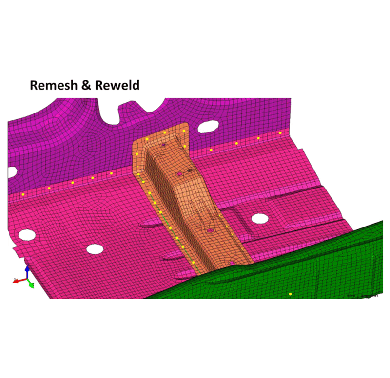
- Auto re-meshing and quality preservation can be carried out seamlessly alongside morphing.
- A single user interface panel now integrates all morphing methods – old and new, the linking process, and all transformation options, greatly improving the user experience.
- New transformation methods such as glide and overwrite have been added, expanding the applicability of morphing methods.
- Post-operations like remeshing and rewelding have been integrated into the morphing process for added convenience.
- The integrated approach to morphing allows for one-time morphing changes or the creation of parameters.
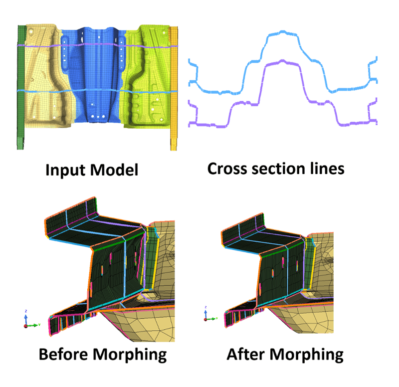
- A section-based morphing methodology has been added, allowing for the morphing of parts or assemblies by cutting sections and controlling them.
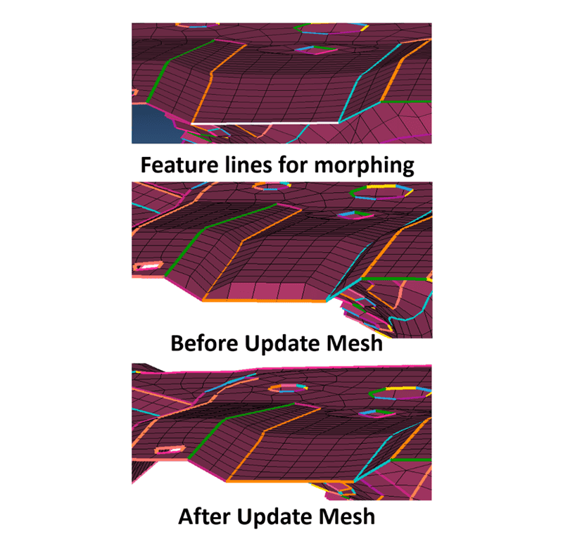
- A feature-based morphing method has also been added, allowing users to reshape parts and assemblies like clay using only feature lines.
- An AI/ML-based morphing technology has been implemented, providing a more intuitive user experience.
- The tool now enables reshaping a model with minimal to zero set-up by controlling its features and sections, eliminating the need to figure out control, deformable, or fixed zones.
- Users can now select only the region to morph, and the tool will intuitively and directly reshape the region.
- During the morphing process, complete control is possible, such as preserving geometric features, cross-sections, and freezing features.
- The precision of morphing is high, with source-to-target matching possible within a hundredth of a millimeter or less.
- The tool can preserve the relationship between parts and assemblies during morphing, with automatic part stack-up adjustment and assembly structure maintenance.
- The morphed features of a part or assembly can update the underlying shell or solid structure automatically.
- The morphing engine utilizes adaptive learning AI/ML technology.
CAD Morphing in MeshWorks provides a proactive approach to the engineering process, allowing for early availability of reference CAD, unlike traditional CAD processes which are reactive and often lag behind product development cycles. Some key features of MeshWorks CAD Morphing include its ability to efficiently and rapidly morph CAD data in a wide variety of scenarios, ultimately resulting in faster delivery of optimized and balanced products to market.
CAD Morphing can be effectively applied at various stages of vehicle development, such as:
- During the early concept stage, where the old vehicle CAD data can be efficiently morphed to fit new styling data and vehicle proportions.
- In the vehicle architecture development phase, where the existing BIW CAD data can be automatically updated to match new sections as defined by the architecture team.
- In the vehicle optimization phase, where the existing vehicle CAD data can be readily updated to align with the optimized results obtained by the CAE team.
Major application area of CAD Morphing are:
Packaging:
- Human factors
- Criteria evaluation
- Vision Study
- Typical Section Development & start data for detailed CAD
- Early Formability & weld access study
- Zone and Limits compliance
- Evaluate Styling theme impact
Benefits:
The revolutionary CAD Morphing feature of MeshWorks enables customers to build models up to 10 times faster than conventional methods, reducing the product development cycle time significantly.
By utilizing CAD Morphing for product development, customers can:
- Develop new vehicle derivatives of existing platforms rapidly.
- Maximize the use of carry-over parts and processes.
- Verify performance compliance at the design stage.
- Obtain complete new CAD reference data.
- These benefits ultimately lead to significant time savings in product development.
Furthermore, MeshWorks' CAD Morphing offers the following advantages:
- Directly working at the mesh level reduces the time required for design modifications, improving overall lead time.
- Automatic control block creation methods require less skill and effort, resulting in time reduction during development and design.
- Parameterized optimization enables fast and efficient design creation.
- CAE models can be easily morphed from parent designs to new concepts or to match design specifications for components derived from different parent designs.
- Numerous parameters can be created for different designs, enabling an easy trial and error method for design correction.
- By treating parts/assemblies as if they were clay, users can achieve any new shape effortlessly.
- Full system level morphing, even for complex aspects, requires no thinking or planning.
- Precision of morphing can be achieved within a hundredth of a millimeter or less.
- During the morphing process, users have enormous control over features and sections.
- The user interface is simple and intuitive with a minimal learning curve, requiring the user to only learn one panel.
- Morphing time has been significantly reduced compared to previous techniques.
- The morphing capability is truly next-generation.
Influence of Morphing on Product Design Process
CONVENTIONAL PROCESS | PROCESS USING MESHWORKS | |
INTERVENTION LEVEL | From the first level | From the preceding stage |
MORPHING CAPABILITY | None / Primitive | High |
CONTROL OVER THE GEOMETRY IN MESH LEVEL | None / Limited | Limitless |
STAGES AFFECTING THE CHANGE IN DESIGN | All | Only in CAE Level |
TIME TAKEN | X (hrs) | X/4 (hrs) |
Auto Control Block Creation
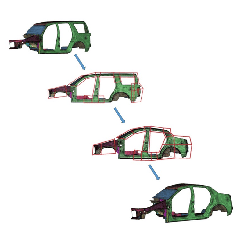
Full Vehicle Morphing
(SUV to Sedan)